|
Dandeman Dan's Toy Page
Toyota 4Runner & Ham Radio Interests |
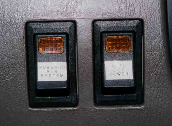
The switch on the left below is self explanatory. It operates the relay for the air compressor. The one on the right? It turns on what I call the Adaptive ECT Control. At highway speeds I like the way Normal mode keeps the transmission in the higher gears as much as possible, but in city traffic, stop and go, or passing situations reaching for the ECT button at a critical moment is too much of a driving distraction. So I came up with the following simple circuit that does it for me. Anytime the brakes are hit, the brake light circuit charges a capacitor in parallel with a reed relay than puts the transmission in power mode for about 20 seconds and then automatically goes back to Normal mode. I find in stop and go/heavy traffic driving it does a good job of keeping the transmission in power mode when I need it, then automatically switches back to normal mode in cruise situations. Only takes a resistor, diode, capacitor and relay to do the trick...
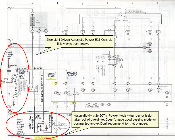
I first tried adding this feature by using the overdrive button on the gearshift which is easy to find by feel. This was a simple change made by using the overdrive indicator light to power a reed relay which puts the ECT in power mode. But this did not work out for my intended purpose as Toyota had other ideas about the operation of the transmission when it is out of overdrive mode. This is recommended mode for towing and therefore the ECT is very aggressive about locking up the torque converter as early as possible and then reluctant and slow about unlocking it, even when you go to full throttle. Not exactly ideal for passing situations. The reason for this mode of operation, i.e. using 3rd gear and locking the torque converter, is much less heat will be generated in the transmission as opposed to 4th gear, unlocked torque converter operation. Both modes yield about the same effective "gear" ratio; but torque converters when operating in heavy torque multiply mode, generates a tremendous amount of heat and is the reason for most transmission overheating.
Okay I admit it.. this is pretty much a wild hair (or is it hare) change, but I like it. For any others so inclined AND have the factory electrical diagrams AND trust their skills to start tapping into the complex wiring in their 4Runner, here's the detail.
Some old wiring harnesses off of GE Master II mobile radios, that I converted to amateur repeater use, provided a source of wire virtually identical in color and size as the factory wiring. Color coding and documenting any changes, becomes important especially later when CRS(Can't Remember Stuff!) sets in. If I have to tap into a vehicle wiring harness, what I typically do is unwrap the harness a ways, carefully strip and solder in the new wire, apply heat shrink to insulate, then lace the harness back up. The end product looks just like another factory wire coming out of the harness.
The added parts below are standard Radio Shack parts. The relays used are Radio Shack P.N.275-233, a 12v SPST one amp contact reed relay specificly chosen for its low (11 milliamps) coil drive current requirement.
Since the relay drive source for the "out of overdrive-power mode" circuit is the Main ECU, a low current draw relay must be used to not place too much extra load on the ECU driver circuit (of unknown drive capability). The reversed biased diode across the relay coil is standard practice to contain any inductive voltage kickbacks from the coil that might cause harm to the driver circuit. I don't recommend adding this circuit, but instead the "stop light activated" circuit below.
The stop light switch activated circuit below, automatically places the ECT in power mode for a brief time period when the brake lights are activated. The brake light circuit charges a 4700 microfarad capacitor wired in parallel with the low current draw relay, and keeps it closed for about 11 seconds. I later added a second 4700 microfarad capacitor in parallel to the one shown to increase the hold time in power mode from 11 seconds to 22 seconds. The diode in series is there to prevent a backflow of the stored power from the capacitors to the stoplight circuit. This would discharge the caps in a hurry and kill the 22 second hold. The 10 ohm resistor, wired in series, serves as a momentary current limiter since 9400 microfarads of capacitance without some resistance, can draw some significant current while charging.
Any connections to an existing circuit in the vehicle should always be wired with sufficient gauge wire to carry the maximum current permitted by the supply fuse (in this case 10 amps). This is to ensure that in the event of a short anywhere along the wire, the fuse will safely blow and prevent any risk of fire.
Toyota 4Runner Electrical Wiring Diagram 2000 Model Pub.No.EWD383U page 5 of 30