|
Dandeman Dan's Toy Page
Toyota 4Runner & Ham Radio Interests |
For some time I have been thinking about installing air shocks on the rear of my 4Runner to accomplish a number of objectives. Recent Toyota 4x4 Off Road forum discussions on the merits of cross linking for increased off road articulation, finally prompted me to proceed with this experiment.
Click on the logo below for a 4x4Wire article on cross linked air shocks.

Preparation for Installation
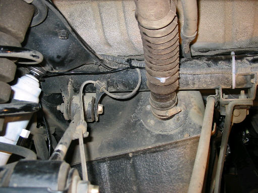
In preparation for installing the new shocks, the spare tire was removed for easier access and some time spent examining the 4Runner shock absorber mounts. Both the upper and lower shocks mounts are made out of the same heavy gauge material as used for the spring mounts and suspension link mounts and, sufficient room is available to accommodate the installation of the Gabriel HighJacker air shocks.
|
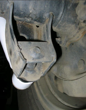
Upper Shock Mount
|
Lower Shock Mount
|
Removal of the Old Shocks
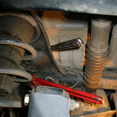
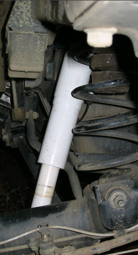
There have been a number of stories about how difficult it can be to remove the rear Toyota shocks, namely in being difficult to keep the shock from turning as the nut on the top stem is being removed. I used a pipe wrench to grab the shock as shown to keep the shock from turning as the nut was removed with a socket and rachet drive. Since the only place the shock outer "cover" cylinder has any real strength is at the very top where it necks down and is joined to the shock stem, that's where the pipe wrench should be placed. Using the wrenches as shown, the shocks came off with no problems at all; it does take quite a few turns to back the nut totally off the the stem.
|
Position of Wrenches to Remove Shocks
|
Spare Tire removed for Easier Access
|
Choice of Air Shocks
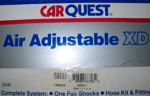
There aren't a lot choices to pick from, either the Monroe or Gabriel HighJacker air shocks. After extensive searching on the Internet, there seemed to be more hits on the use of the Gabriels, and no war stories were found so I decided to go with them. CarQuest Auto Parts carries the Gabriel HighJacker Shocks, repackaged as the CarQuest Air Adjustable XD. CarQuest lists part number SHK50897 as the correct shock for the Toyota 4WD 4Runner rear axle. The ends of the box that the shocks came in, are pictured below for easy identification.
|
Gabriel Shocks via CarQuest Auto Parts
|
CarQuest SHK# 50897
|
Comparison to Original Toyota Shocks
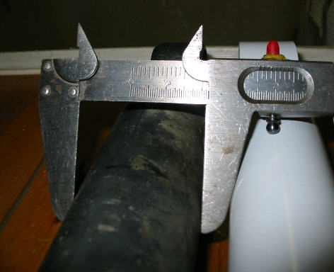
Shock Tube DiameterThe narrower diameter is probably necessary to allow room for the air bladder and at the same time, keep the outer diameter of the overall shock small enough to avoid clearance problems.
|
Toyota Shock Tube Width (~ 1 3/4")
|
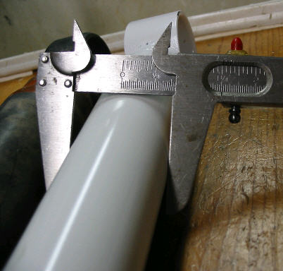
Gabriel Shock Tube Width (1 1/2")
|
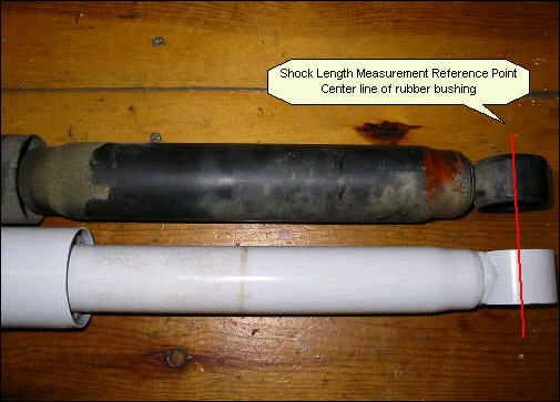
Shock Length Comparison
As shown in this photo, the shocks are 1 1/4 inches longer at full extension compared to the Toyota original shocks. This should allow some extra droop, but hopefully not so much that problems such as, bending the rear sway bar and the drive shaft hitting the gas tank shield, that occurred with the 3.5" longer Bilstein Rear 1991-1997 Land Cruiser shocks B46-1478 tried by others.
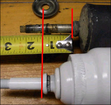
For reference, the original equipment shock (Tokico #48531-3D011) measures 19 3/4 inches from the stem shoulder reference point shown below to the center line of the rubber bushing on the lower shock mount eye. The Gabriels measured the same way are 21 inches long. The minimum fully compressed length for both shocks is 12 1/2 inches.
|
Gabriel Shock Length versus Original Shocks
|
View of the lower portion of the shocks
|
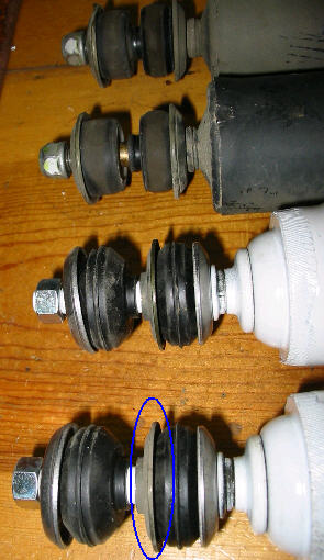
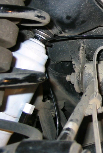
Shown below in order, first are the rubber bushings and hardware that came with the Gabriel Shocks. The original Toyota metal bushing circled blue was reused with the new shocks as this intermediate piece did not come with the new shocks. The second photo shows the upper portion of the installed shock. Note the shock air fitting is turned inward, as this orientation provides more protection and clearance. Lastly, shown is the lower view of the installed shock.
|
Shock Mounting Hardware
|
Installed, Upper View
|
Installed, Lower View
|
|
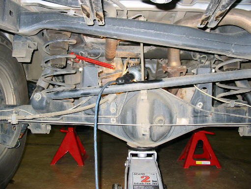
Effects of Additional Shock Length
Shown below is a quick check of the articulation. There's some decent extra droop with the additional shock length. I also noticed an interesting observation while pulling up the incline. With my original tires at 55K, the grip on wet dirt is not so good. I stopped the vehicle as soon as I begin to get wheel spin and got out to give it a look. The vehicle did not spin at all on the wet leaves/ground until the shock hit full extension (easy to check as the air bladders can be felt at the bottom of the outer metal tube when fully extended) so, this suggests as discussed on the 4x4Wire Toyota Forum, that there is weight transfer from the compressed shock to the extended shock. |
|
|
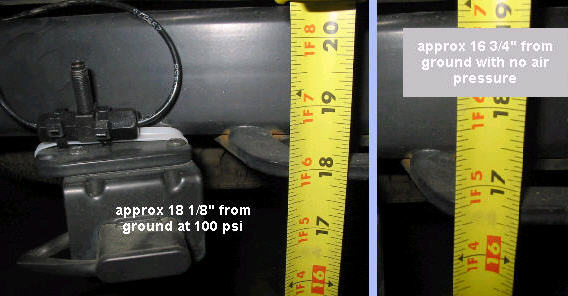
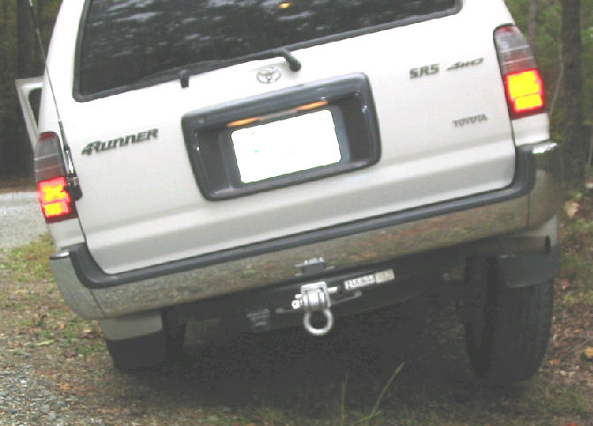
Lift, measured at the Trailer Hitch Lift (as measured at the rear hitch, is about 1 3/8" at 100psi, the maximum pressure of my onboard air compressor. The shocks are designed to accommodate a maximum of 200psi. Also shown is the temporary standard plastic fitting and tubing that is being used until the permanent variable control pressure system installed. |
Given the satisfactory preliminary results, the next step was to proceed with installation of the second phase of this project which allow adjusting the air shock pressure from inside the cab, by changing an air regulator setting.
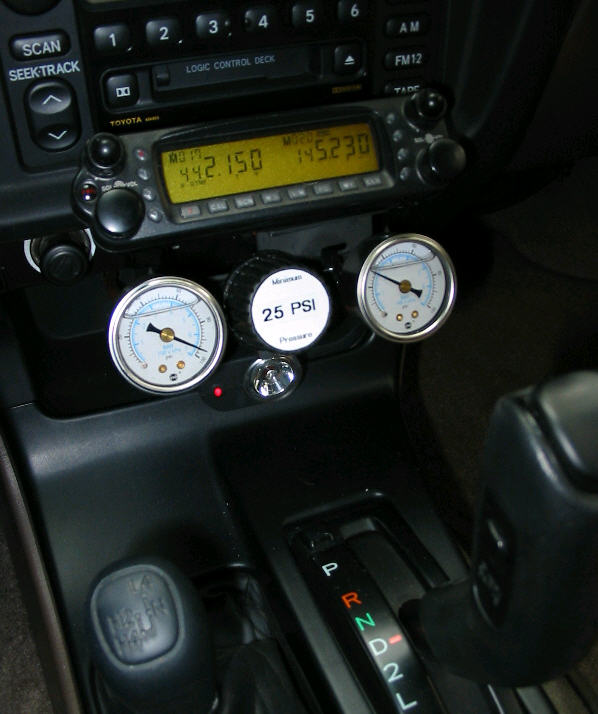
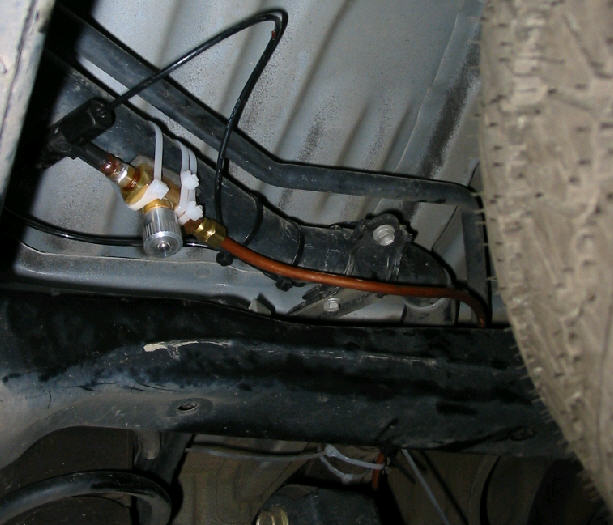
Given that the air shocks have a minimum air pressure requirement of 25psi, it was decided to use an air regulator instead of electric air valves. The regulator is a much cheaper solution and allows any pressure to be set in the shocks with a twist of a knob as shown below. For example while on road, the vehicle can ride at normal height and with the cross linking effect disabled by having only the minimum required air in the shocks to prevent air bladder damage. For off road, the air pressure can be set to the 100psi, to get the maximum effect of the cross linking and, additional clearance at the rear of the vehicle.
Installed Air Pressure Regulator System
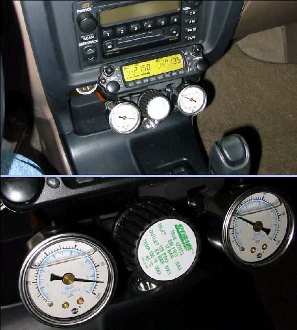
Shown below are the regulator components with the Grainger part numbers. The mini regulator and gauges are pretty much a no brainer, however the check valve and the air metering control valve need a little explanation which follows below.
Regulator System Components
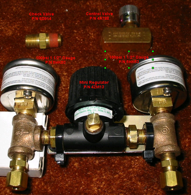
The check valve shown was installed in the air line between the compressor air storage and the regulator, so if the compressor air storage is drained down, air pressure currently in the shocks will stay, and not drain back through the system.
Final Installed View of Air Pressure Regulator System
Installing the Air Lines
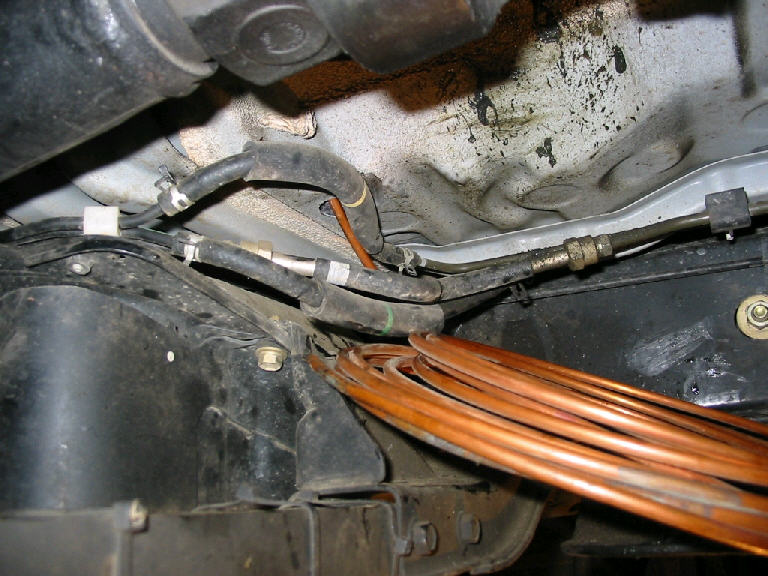
A rubber grommet hole just forward of the gas tank was used to run the lines from the air shocks and compressor air storage to the in cab regulator. By placing the roll of soft copper pipe as shown and uncoiling, the bend on the uncoiled line was perfect for following the desired path underneath the floor carpet up to the center console. This part of the job could be done much easier with two people, one below to work in the grimy, greasy area near the drive shaft, and the other person inside the vehicle, helping work the line up to the desired position. Also, the use of plastic flexible line would be even easier to install, but my preference was to use the soft copper metal piping.Rubber Plug Hole Near Gas Tank Used to Enter the Body
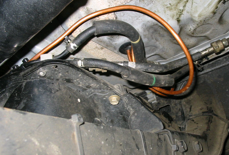
Lines Complete with Rubber Plug back in Place
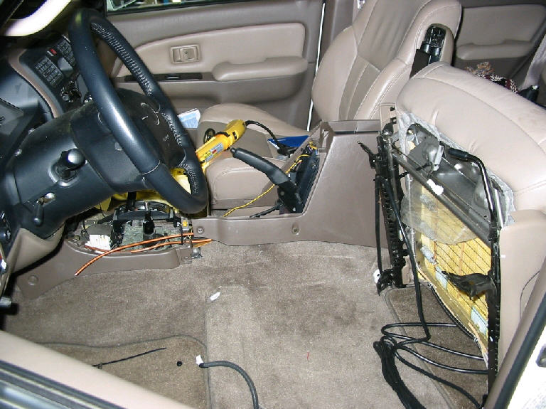
To facilitate routing the air lines, the driver's seat was unbolted and moved back out of the way. The console storage unit was also unbolted as shown.
Driver's Seat and Console Unbolted and Shifted to Facilitate Running Lines Under Carpet
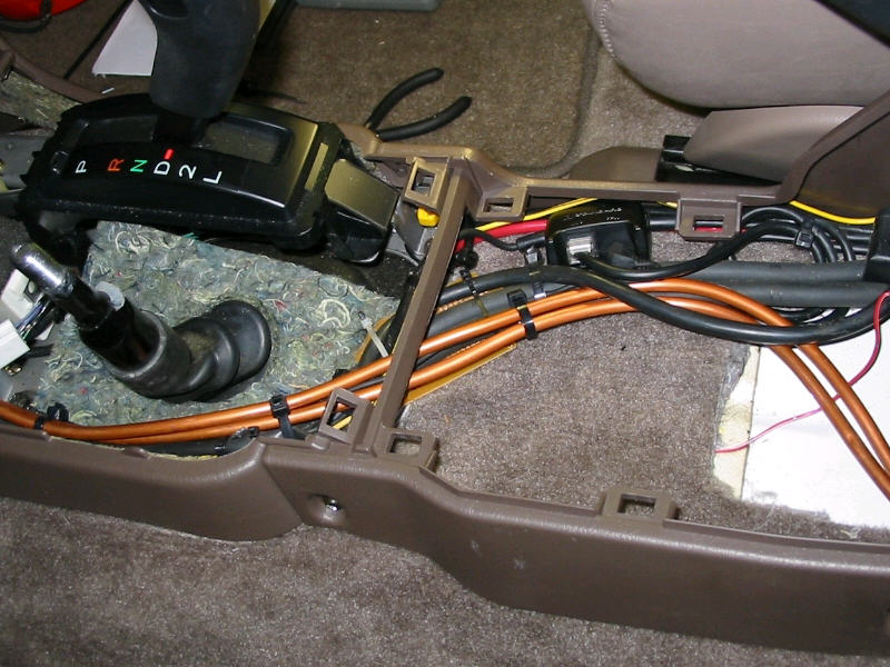
My console area was already pretty full with two #2 gauge welding cables running through to supply the 120v AC inverter and other cables and components for the mobile amateur radio system. This wiring and the air lines must be routed over to the right side of the console as shown to avoid interference when the console section with the cup holders is reinstalled.
Lines Routed Through Console to Clear Bottom of Cup Holder
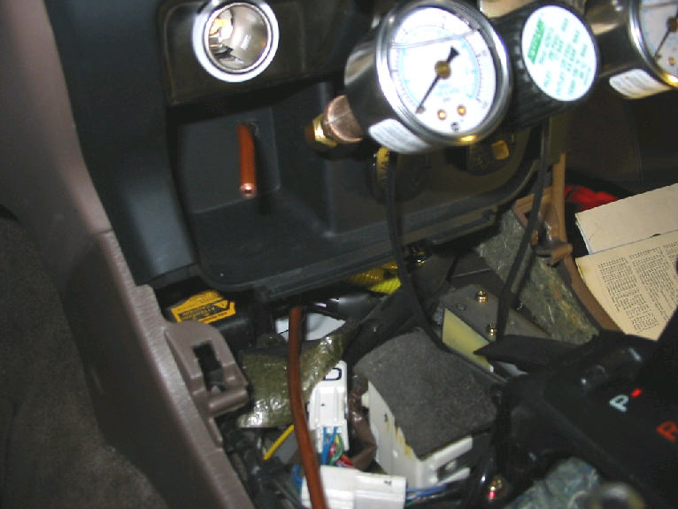
Using solid copper line becomes a bit tricky on the next step which is to get it behind the upper part of the center console panel and through the hole drilled for the air line. This was done by twisting the line over as shown, and working it behind the panel, and then through the hole.
Twist Line over This Way to Get Under Center Console
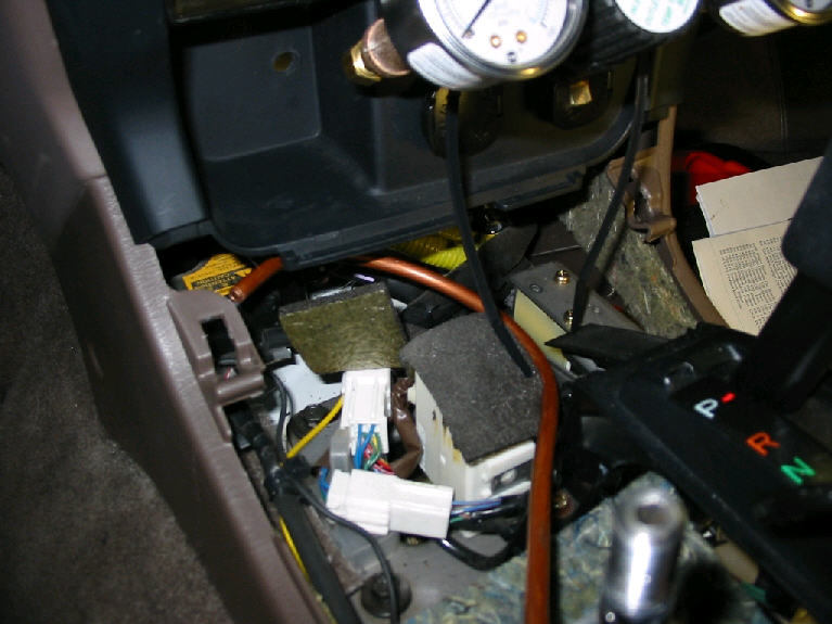
And Back Through Hole Drilled for Air Line
Air Metering Control Valve
The air metering control valve is critical to proper operation of this system. The control valve is nothing more than an adjustable needle valve, but performs some important functions.
If you have ever rode in an air bag or air shock equipped vehicle with an air pressure monitor gauge, you probably noticed that the pressure can momentarily come close to doubling when the vehicle hits a bump where back end tries to bottom out. Also the air gauge pressure is bouncing all over the place as the shocks are doing their thing.
The air pressure regulator used in this system not only will add air if shock pressure falls below the setting, but also will bleed air if the shock pressure is above the pressure setting. Without some form of protection, the regulator would be constantly over correcting. Therefore, the metering valve is a must, to prevent the regulator from bleeding and adding air on these pressure transients. The air pressure regulator sees only the "average" pressure in the system when the needle valve is set to a very small flow rate.
After some trial and error testing, the correct setting was determined to be with the valve adjusted such that only very minor movements of the pressure gauge are visible , during major vehicle bounce with the 100psi maximum air pressure. With the regulator not constantly overcorrecting and either loosing and adding air, the compressor does not have to stay on all the time as the desired air pressure stays in the shocks.
Cross Connected (linked) Shock Air Lines
The air metering control valve is mounted where it can reached through the left rear wheel well for adjustment as shown below.
This is also the point where the air line from each shock comes together to make the cross linked configuration. Originally, I had considered replacing the very small diameter air lines with larger compressor type flexible air hose, thinking that some additional external, compressible air storage would be needed to prevent a "pogo stick" effect (or severe bouncing from essentially too high an equivalent spring rate) from the air shocks. I have experienced this effect in a friend's full size pick up truck with air bags and assumed that air shocks might exhibit the same characteristic, due to the very small compressible air space inside the air shock bladder. However, in ride testing with the shocks at 100psi, I felt no "pogo stick" effect at all, and decided to leave the small diameter air lines.
Location of the Air Metering Valve and Cross Connection
Heres another ramping shot with the right rear fully drooped and off the ground.
Rear Axle Droop, Air Shocks at 100psi
View of Axle in relation to Body
Clearance Check with the Longer Shocks
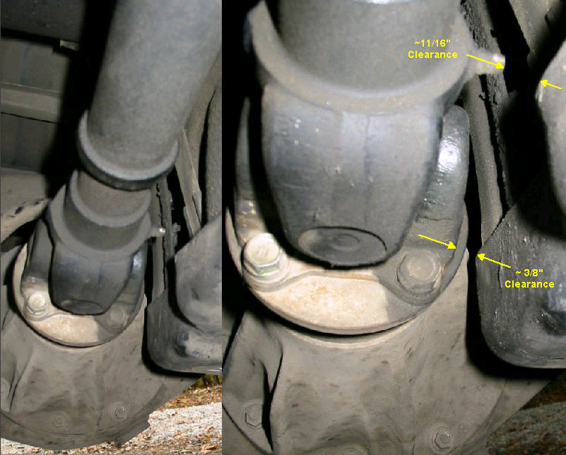
Drive Shaft to Fuel Tank Shield
With the left rear tire stuffed and the right tire off the ground, there is approximately 3/8s of an inch clearance remaining between the drive shaft and the gas tank shield. The additional 1 1/4 inches maximum extended shock length is pretty much the limit, considering a little bit of clearance needs to be left for further shifting due to the rubber bushings in the suspension.
Drive Shaft Clearance to Gas Tank Shield
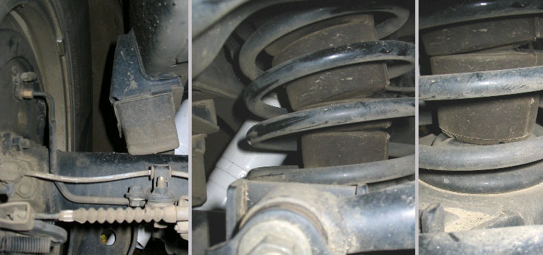
Axle Travel Bumper Stops
As shown here, the upper limit on further axle travel looks good, with travel being limited by both the outer rubber axle stop and the inner spring rubber cone.
Bump Stops with the Axle Fully Stuffed
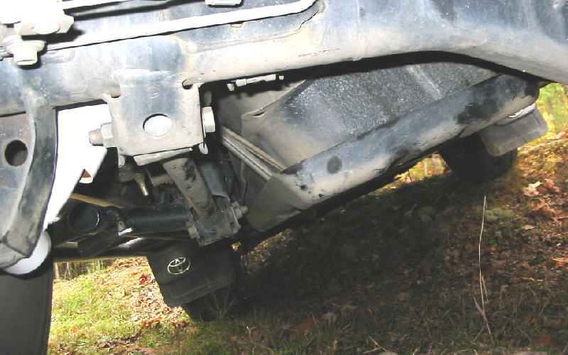
Fuel Tank Shield Corner Exposure
This view with the left tire stuffed, shows the vulnerability to the fuel tank shield to rocks due to the corner hanging down below everything else. Will have to remember this on the trail.
Also, in looking closely at the lower trailing arm and it's bushings, it appears that amount of twist is within acceptable limits and is totally absorbed by the rubber bushings.
Fuel Tank Shield Exposure with Left Rear Axle Stuffed
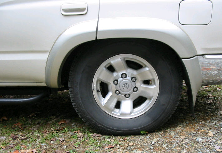
View of Left Tire Stuffed
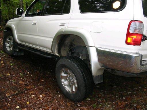
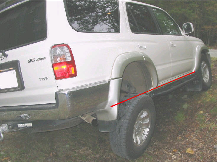
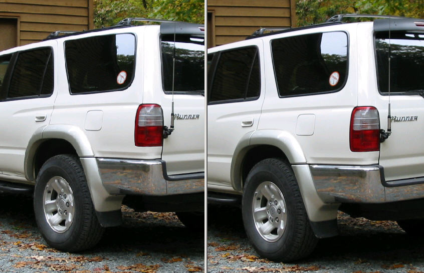
Rear Lift Comparison at 100psi and 25psi
The difference in rear height is apparent especially when viewing the flare in relation to the tire. It would be interesting to see how much lift would be achievable (and what the ride characteristics would be) with the full 200psi limit of the shocks. I don't have a means of getting the air pressure up that high. Lift (as measured at the rear hitch), is about 1 3/8" at 100psi.
Rear Lift (left photo at 100psi) and (right photo at 25psi)
So far I am pleased with the results..
While there is no substitute for a locked rear axle on uphill twists, in preliminary testing on wet ground I did not get wheel spin at until the shocks hit full extension, there that may be some tangible traction improvement for the additional tire loading on the lifted tire with the cross linking. I plan to find some slick uphill twists where the tires are just at their limit of traction, and play with the in cab controls to see if bumping the air pressure up for more weight transfer to the unloaded side, does in fact make any noticeable change in tire traction.
With more production vehicles getting air suspension assist, there may be a larger selection of parts to play with sometime in the future.