|
Dandeman Dan's Toy Page
Toyota 4Runner & Ham Radio Interests |
With space under the hood and the underside at a premium, and to keep added weight down, it was decided that the rock sliders should serve double duty, with their secondary purpose as an air storage tank. The volume provides adequate buffer for compressor operation with an automatic pressure switch. When airing up, I have found the storage volume and compressor output to be more than adequate to pump each tire back up with no waiting for "compressor catch up". The compressor itself is tucked high behind the front bumper as shown below.
Air Storage "Tank" Location and Considerations
In using the rock sliders as an air tank, I had several concerns I thought necessary to address. Based on my experience with the home shop compressor (a 12 gallon model), internal corrosion and water accumulation seems to plague any air compressor tank. The inside of that tank looked pretty ugly when I looked inside while replacing a sticking check valve; and this tank is regularly drained. I suspect the problem is more pronounced in high humidity areas such as the Southeast. Accordingly on this project, I injected about a half pint of POR-15 through the air fittings and rotated the bars from end to end to coat them internally to prevent corrosion. Given that there is no one low point to drain any accumulated water out of this system, I focused on designing the system to trap and blow out moisture before it actually gets pumped into the bars. Since there is approximately 6 feet of 1/4" copper line running from the compressor to the entry point on the bars, this works as an "after cooler" to bring the temperature of the compressed air back down to ambient. This also means any moisture in the compressed air is going to largely condense out in the line.
|
|
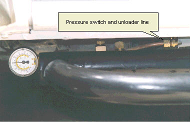
Unloader Pressure Switch
To take advantage of this, an "unloader" type pressure switch was used with a 1/8" diameter unloader line connected to the 1/4" supply line at a low point, so every time the compressor cuts off, there is a "blow down" of the supply line to clear out any accumulated moisture. In this photo, you can see a pressure gauge, pressure switch and the unloader line behind the left bar. In addition to the automatic compressor switch, there's an ASME approved pressure relief valve (visible in frontal pictures below showing the compressor mounting).
|
|
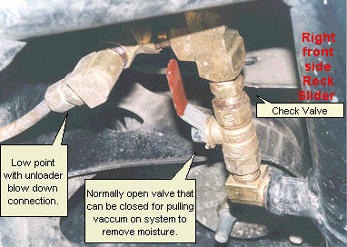
Another way to evacuate moisture
Since I couldn't be absolutely certain that this would keep moisture from accumulating, I also added a little extra plumbing to purge out moisture another way. The air compressor, a Thomas TA4101DC, can be used as a vacuum pump per the manufacturer. A couple of extra valves (one of which, along with the check valve is visible on the right) and an extra quick disconnect on the intake side of the compressor was added so I can occasionally use it to evacuate the system to boil out any moisture in the system. The Thomas compressor is rated to pull 27.5" of vacuum which is marginal for this application to fully evacuate to ensure all moisture removed. You really need a multistage vacuum pump (very expensive!) expressly designed for this purpose; so this aspect is a make do with the available compressor... At this level of vacuum, any water in the system will boil at 106 degrees at sea level. With a little help from higher altitude and doing this with the vehicle exposed to the sun on a hot day, it will probably do the job.
|
|
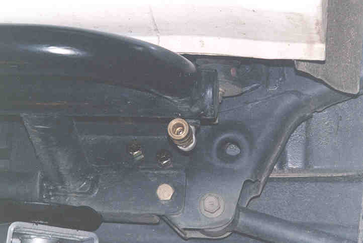
Air Hose Quick Disconnect
The details of the cradle bolting to the rear suspension trailing link mounting point (using existing holes) and the location of the quick disconnect for the air hose are shown here.
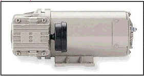
A Thomas TA4101DC air compressor provides the supply. An Intercomp Racing Fill,Bleed & Read Air Gauge with 25' of air hose completes the system.
How much compressor do you need?
Click on the compressor below for more information.
Air Compressor Location
With no room under hood for a compressor of this size, it was decided to use space available between the radiator and front bumper for the air compressor. Since a custom front receiver hitch and skid bar assembly was currently under construction, adding a mounting pad for the compressor was relatively easy. The yellow hose connects the compressor air intake to its air filter which is located up high next to the engine air filter intake.
The compressor is shown in place below. On the floor is a weather cover for the compressor, made from a Wal-Mart plastic mail box which was the perfect shape. Heavy screening was added to the front of the radiator to keep big stones and "Nebraska monster bugs" out of the radiator. The acceptability of the compressor location and the skid bars below do reflect the type of off roading we do. This vehicle has two equally important purposes as a long range traveler and, off roading at our journey destination, principally in the Rocky Mountains. We don't do any serious mudding or high water which would preclude installing in this area.
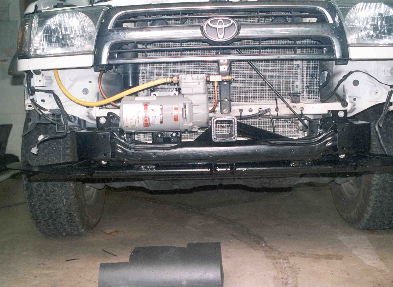
Compressor Mounting Location
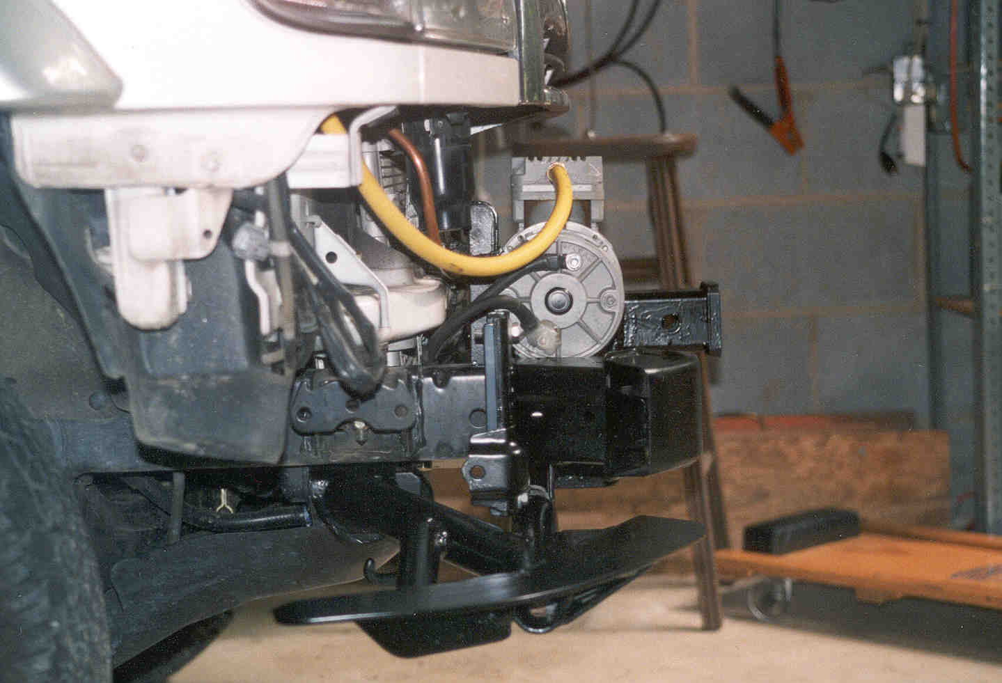
Side View of Compressor Mounting